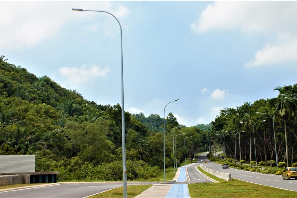
Uniformity lighting in dry and wet roadway
Uniformity lighting in dry and wet roadway
Introduction
Road lighting is an important part of urban infrastructure. It plays an irreplaceable role in ensuring the safety of pedestrians and vehicles and improving the city’s nighttime landscape. If you have a road lighting project and need to purchase street lamps (ZGSM different series street lamps), you need to pay attention to how many watts of lamps you need to buy to meet the project requirements, but you don’t know much about lighting requirements, such as luminance, illumination, uniformity, etc. This article will focus on some road lighting standards that need to be paid attention to in motor vehicle lane lighting, including luminance/illuminance, uniformity lighting and glare on dry roads. We will also mention the changes in luminance/illuminance, uniformity and glare on wet roads. In addition, there is an indirect connection between illuminance and luminance. Note that it involves the reflectivity of the road in both dry and wet conditions. ZGSM hopes that these will help readers better understand the basic common sense in road lighting, and then optimize their own lighting and project design.
Standards for road lighting
There are evaluation indicators for road lighting for motor vehicles and pedestrian roads. The evaluation indicators for motor vehicle traffic road lighting include average road surface luminance, road surface brightness uniformity, glare limit, and ambient ratio. The evaluation indicators for pedestrian road lighting include average road surface illuminance, minimum road surface illuminance, and vertical illuminance. The following are specific lighting requirements for two common roads, which refer to the EN13201 standard (More about EN13201 for road lighting design). It should be noted that there are certain differences between EN13201:2004 and the latest EN13201:2015 standards. The former has lighting classes ME1, ME2, … ME6, and MEW1, MEW2, … MEW6, while the latter only has M1, M2, … M6.
| Lighting class | dry | wet | TI in % | SR | ||
| Lav in cd/m2 | Uo | UI | Uo | |||
| M1 | 2 | 0.4 | 0.7 | 0.15 | 10 | 0.5 |
| M2 | 1.5 | 0.4 | 0.7 | 0.15 | 10 | 0.5 |
| M3 | 1 | 0.4 | 0.6 | 0.15 | 10 | 0.5 |
| M4 | 0.75 | 0.4 | 0.6 | 0.15 | 15 | 0.5 |
| M5 | 0.5 | 0.35 | 0.4 | 0.15 | 15 | 0.5 |
| M6 | 0.3 | 0.35 | 0.4 | 0.15 | 20 | 0.5 |
| Lighting class | Average horizontal illuminance Eav in lx | Minimum horizontal illuminance Emin in lx | Minimum horizontal illuminance Emin in lx | Additional requirement | |
| Ev,min in lx | Esc,min in lx | ||||
| P1 | 15 | 3 | 20 | 5 | 3 |
| P2 | 10 | 2 | 25 | 3 | 2 |
| P3 | 7.5 | 1.5 | 25 | 2.5 | 1.5 |
| P4 | 5 | 1 | 30 | 1.5 | 1 |
| P5 | 3 | 0.6 | 30 | 1 | 0.6 |
| P6 | 2 | 0.4 | 35 | 0.6 | 0.4 |
We can see that the motor vehicle lane lighting has a U0 requirement for wet roads, while the P lighting class does not have uniformity requirements for roads (including wet roads). When your project has uniformity requirements, the lighting simulation should meet the corresponding requirements, which also includes the U0 requirements for wet roads. In addition, we see in the table that there are two indicators in the requirements: "average luminance" and "average illuminance". Many people do not understand this very well. We will explain these two indicators in detail in the next section. Motor vehicle lanes also have requirements for glare. If you are interested, please check our blog “How to reduce glare?”.
More about luminance and illuminance
The calculation formula of illuminance is E=dΦ/dA, where E is illuminance (unit: lux), Φ is luminous flux (unit: lumen lm), which represents the total light output of the light source, and A is the illuminated area (unit: square meter m²). From the formula, we know that illuminance describes the luminous flux (Wattages vs luminous flux) received per unit area, which only reflects "How much light reaches the road surface".
The formula for calculating luminance is L=dΦ/dΩ/dA/cosθ, where L is brightness (unit: candela/square meter cd/m²), dΩ is solid angle (unit: steradian sr), which indicates the range of the light cone in the viewing direction, and dθ is the angle between the viewing direction and the normal of the road surface. Through the formula, we know that brightness describes the luminous flux emitted (or reflected) per unit projection area and per unit solid angle. The human eye observes the light source from one direction. The ratio of the light intensity in this direction to the area of the light source "seen" by the human eye is defined as the luminance of the light source, that is, the luminous intensity per unit projection area. The calculation formula is relatively complicated (involving calculus). In order to help everyone better understand it, we have given the following figure. We assume that the luminous flux emitted per unit projection area remains unchanged, so the size of the light intensity depends on the size of the solid angle of light received. We can see that when the eyes are away from the luminous surface, this angle is getting smaller, that is, the light received by the eyes is decreasing, and the surface of the object seen by the eyes is getting darker.

In road lighting, street lamps shine light onto the road, and the illuminance cannot accurately reflect the road luminance observed by personnel. Illuminance has nothing to do with the reflective characteristics of the road surface itself, while luminance depends on illuminance and the reflective characteristics of the road surface. For dry asphalt pavement and wet pavement, if the illuminance is the same, the road brightness observed by the driver will also be very different due to their different reflective characteristics. Through the calculation formula, we can know that if the reflectivity of the road is not considered, the conversion between luminance and illuminance is related to the observation angle and observation distance. If reflection is taken into account, we can get a brightness factor(Weighted Average Luminance Coefficient) Q0, which is determined by the road material, roughness and wetness according to the EN13201 standard. PS: The premise is that the distance and angle of the road observed by the driver are certain. For example: if the asphalt road E=20lx, if it is dry, Q0 is 0.10, and the luminance L=20*0.1=2cd/m2. Under the same illumination, the wet pavement Q0=0.20, that is, the luminance L=20*0.2=4cd/m². The following is the R-table which shows the reflectance characteristics of different pavement types.
| R-Table | Weighted Average Luminance Coefficient | Description |
| C1 | 0.10 | Concrete, CIE C1 |
| C2 | 0.07 | Asphalt, CIE C2 |
| N1 | 0.10 | CIE CLASS = 1 - very diffuse |
| N2 | 0.07 | CIE CLASS = 2 - concrete |
| N3 | 0.07 | CIE CLASS = 3 - asphalt |
| N4 | 0.08 | CIE CLASS = 4 - glossy asphalt |
| NZN4 | 0.09 | Diffuse chip seal surface |
| NZR2 | 0.09 | Glossy polished asphaltic surface |
| R1 | 0.10 | Mostly diffuse reflectance properties characteristic of Portland cement or asphalt surface with a minimum of 15% of the aggregates composed of artificial brightener aggregates. |
| R2 | 0.07 | A combination of diffuse and specular reflectances characteristic of asphalt surfaces with aggregate composed of a minimum of 60% gravel of size greater than 10mm. Also asphalt surfaces composed of 10-15% artificial brightener in aggregate mix. |
| R3 | 0.07 | Slightly specular reflectance typical of asphalt surfaces with dark aggregates, rough texture and some months of use. This surface is common in the United States |
| R4 | 0.08 | Mostly specular surface typical of very smooth asphalt texture. |
| UKR2 | 0.05 | Porous Asphalt (UK) |
| W1 | 0.11 | Wet surface |
| W2 | 0.15 | Wet surface |
| W3 | 0.20 | Wet surface |
| W4 | 0.25 | Wet surface |
| ZOAB | 0.10 | CIE Class 2 Dutch Porous |
Why care the uniformity lighting for both dry and wet roadways?
A water film will form on the surface of a wet road, covering the rough asphalt/concrete surface. The water film smoothes the originally uneven road surface, turning it from diffuse reflection to specular reflection. When light (street lights) shines on a wet road, a directional reflection will be formed (i.e., the angle of incidence ≈ the angle of reflection). Similarly, the light from the headlights will also be concentrated and reflected to the driver's eyes, causing areas that flicker. However, dry roads will not have the uneven light distribution (extremely bright and dark) of wet roads due to the scattered light of diffuse reflection.
The following figure shows the lighting effect of street lamps on roads of different materials. We can see that the light distribution (What's light distribution?) is relatively uniform on roads of C1 and R3 materials, while the mirror reflection is obvious on the wet road surface of W4. The luminance of the area connecting the street lamp and the driver is significantly higher, while the brightness of the lane far away from the lamp is significantly lower, so the uniformity is also poor. We conclude that on dry roads (C1), light is scattered by the rough surface, and there is a certain brightness in all directions without glare. On wet roads, the smooth surface of the water film causes concentrated reflection of light, and the reflected light intensity in local areas is much higher than the surrounding area.
How to use lighting design to get better uniformity?
In order to obtain better uniformity lighting, it is necessary to explain how U0 and UI are calculated in road lighting. In road lighting, Uo (average luminance uniformity of the road surface) is calculated by the ratio of the minimum luminance to the average luminance, that is, Uo=Lmin/Lav. If there are two lanes, the two lanes need to be calculated separately, and the smaller value of the two uniformities is used to evaluate whether the overall brightness uniformity of the road surface U0 meets the requirements. UI (longitudinal uniformity of road surface brightness) is the ratio of the minimum luminance to the maximum luminance along the longitudinal center line of the road, UI=Lmin/Lmax. Similarly, if there are two lanes, UI takes the smaller value of the two as the final result. The two reflect the uniformity of road lighting from different dimensions. The former reflects the uniformity lighting of the entire road, while the latter focuses on the uniformity of the driver's travel direction (lighting continuity).
Choose the right light distribution for uniformity lighting
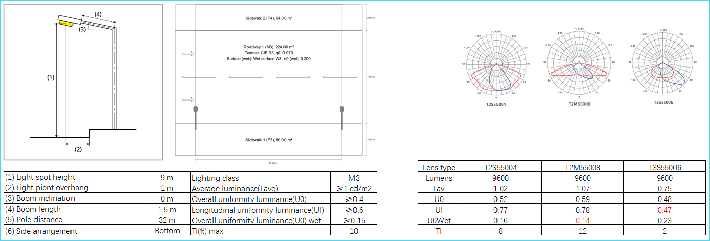
We compared U0, U0W and UI of different lenses under the same road conditions. The layout of the road is a 7-meter motorway with 2-meter sidewalks on both sides. The road surface is CIE R3, and the wet road surface is W3. From the table, we know that Q0=0.07 and Q0W=0.20. The luminaire is a single-sided arrangement, where the distance between the luminaire and the motorway is 0.5 meters, and the boom length is 1.5 meters. The height of the lamp pole is 9 meters, the distance between the lamp poles is 32 meters, and the boom angle is 0°. With this luminaire arrangement (More details about luminaire arrangement), we compared three light distributions and listed the results in the table below. When Rifle series 60W is equipped with T3S55006, although U0wet meets the requirements, UI does not meet the requirements. This is because the vertical light distribution of this lens is unreasonable, resulting in low luminance in the middle of the two luminaires, which in turn leads to a very low uniformity UI. If equipped with T2M55008, U0wet does not meet the requirement of uniformity lighting. Rifle 60W street light is equipped with T2S55004. Due to its reasonable light distribution, its U0, UI, and U0wet can meet the lighting requirements of M3.
Set reasonable luminaire arrangement for uniformity lighting
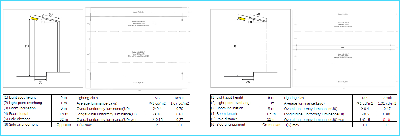
We also tested the effects of different luminaire arrangements on U0, U0W and UI. In the previous section, we learned that the use of ZGSM Rifle series (Go and check ZGSM Rifle series street lights) with T2M55008 in the side arrangement cannot meet the U0wet requirement. If it is a 30W double-sided arrangement, the result is obvious, U0wet can reach 0.42, which is significantly higher than the requirement of 0.15. However, the cost is also very high, so it is recommended to improve U0wet by optimizing the lens. Of course, if it is a two-way with 4 lanes road, then this solution is still feasible. In the figure below, we tested the four-lane road, and the results show that U0Wet can reach 0.27, which can fully meet the driver's uniformity requirements on rainy days. It is worth noting that we do not recommend the median arrangement (two lamps on one pole), although its cost is relatively low, but the U0wet result is not ideal which can not get uniformity lighting . In addition, the layout of your roadway (pole height, overhang, boom inclination, boom length, pole distance) also has a great impact on the U0 result, which we will not elaborate on here due to space limitations.
ZGSM LED street lights
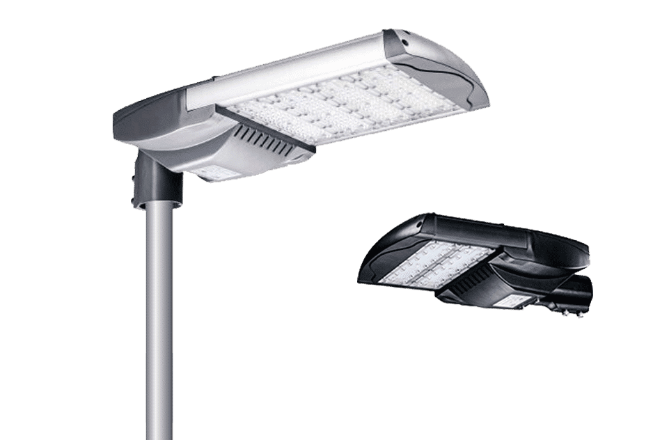
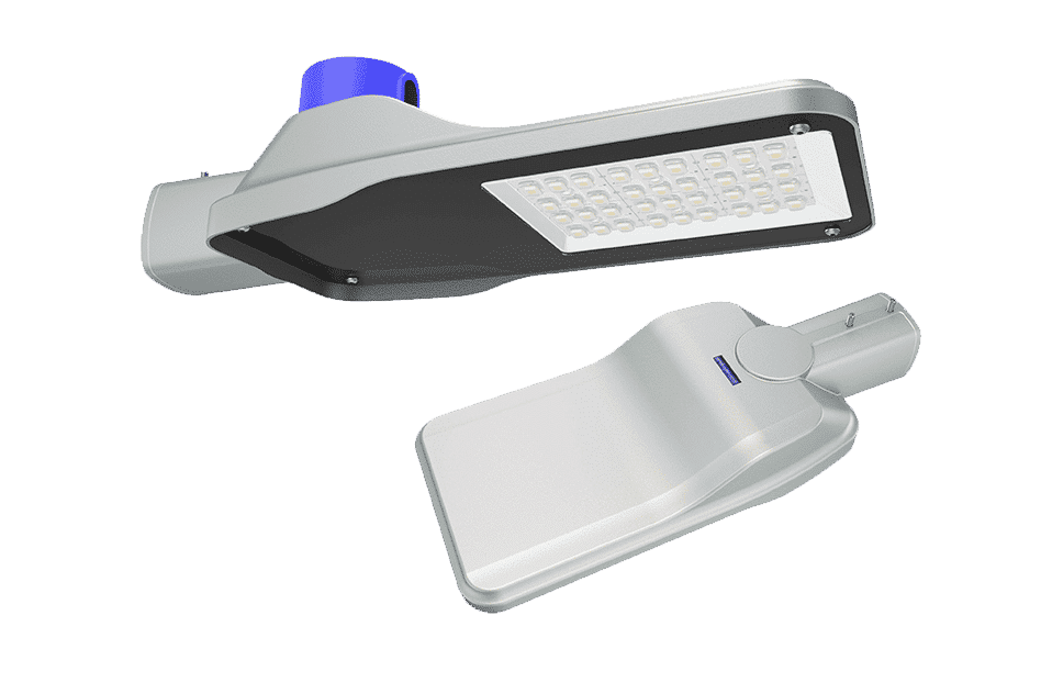
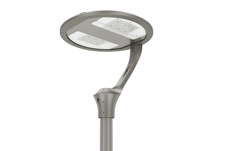
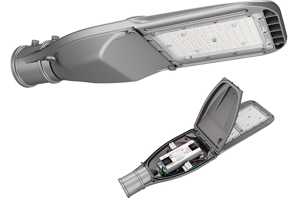
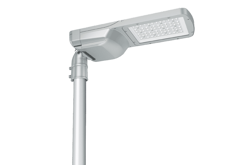
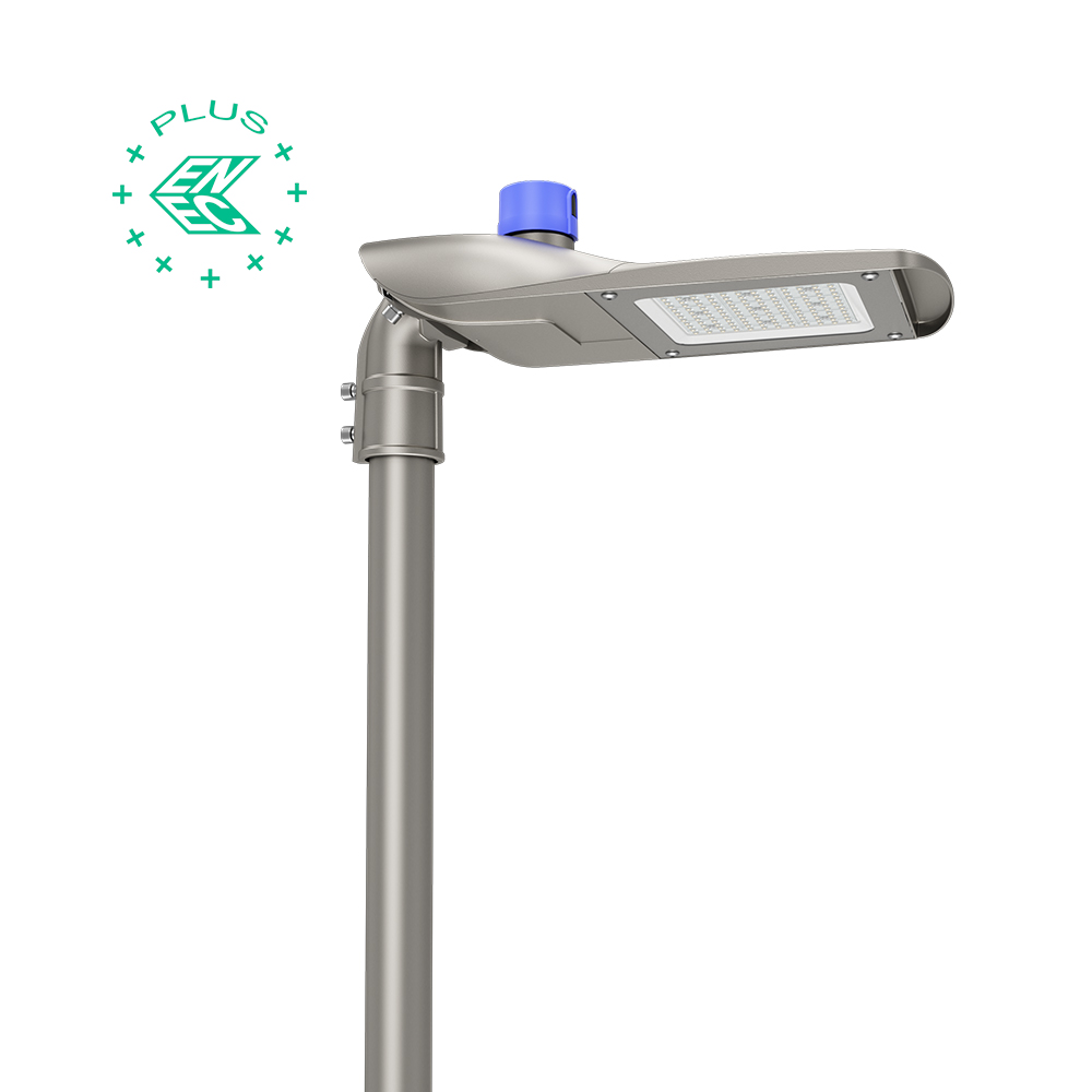
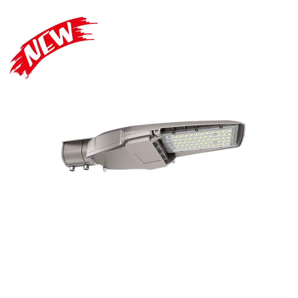
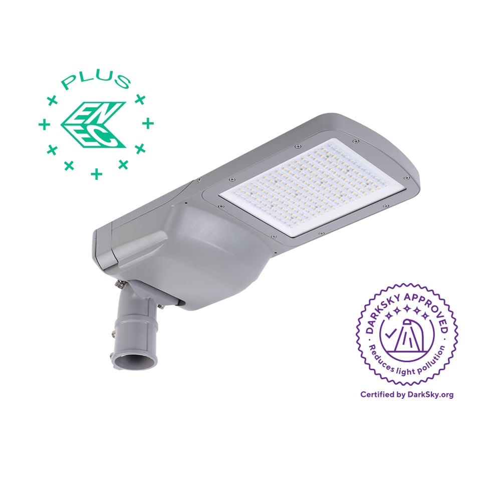
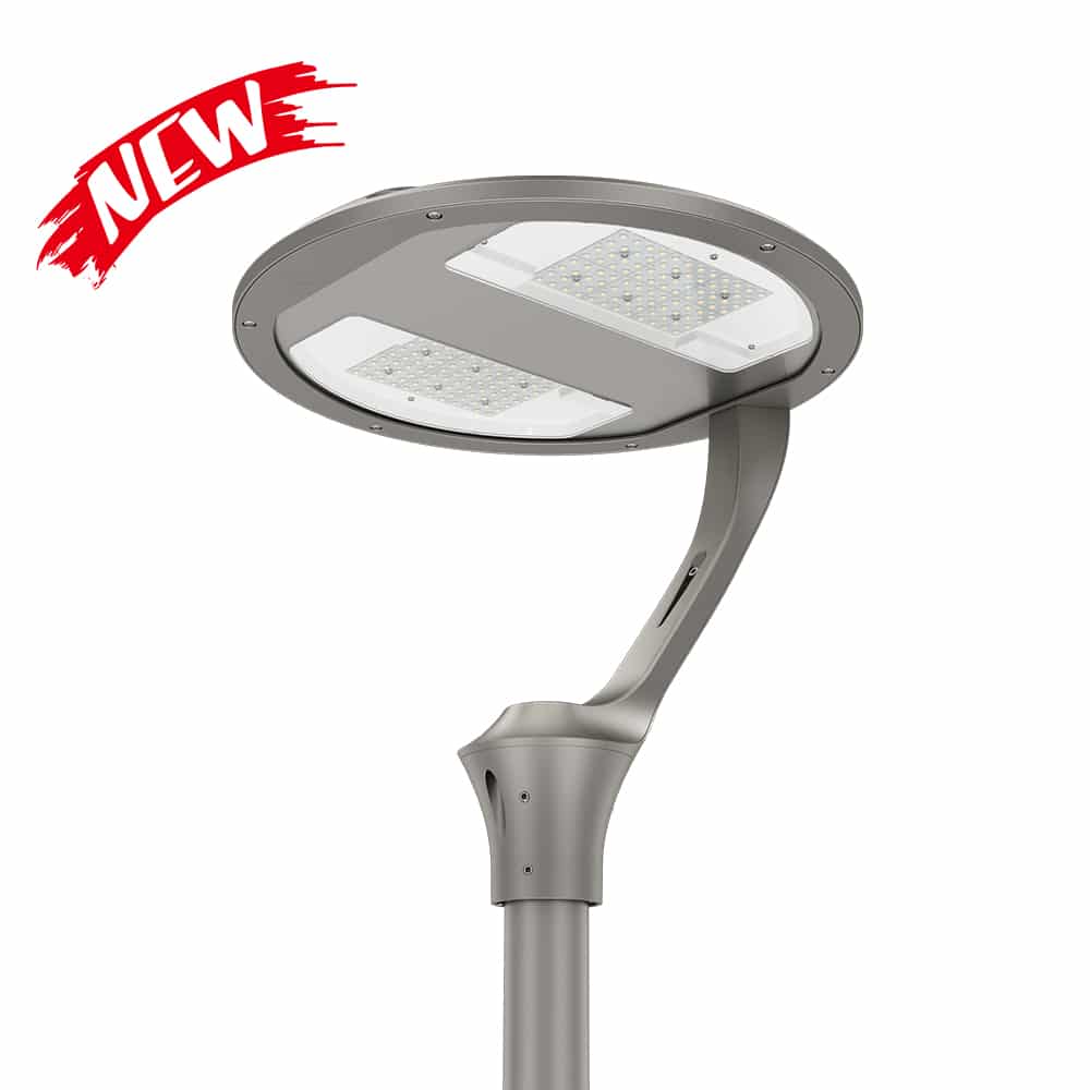
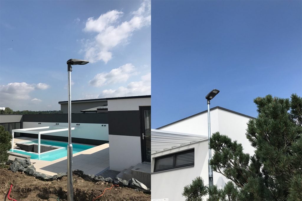
As a company engaged in the production and sales of LED lamps for nearly 20 years, ZGSM always analyzes and thinks from the perspective of customers, whether it is the innovation of lamp appearance, the diversification of LED drivers, the brand of LED chips and the selection of lamp efficiency. At the same time, we also pay attention to relevant industry standards, including the requirements of EN13201 for uniformity lighting (Check the find solution to improve the uniformity in other outdoor lighting) of roads. It is because ZGSM's LED street lights have a reasonable structural design, and with different lenses, they can meet the requirements of U0, U0wet and UI for different roads. The following are several street lights of ZGSM. If you are interested, you can click on the pictures for more information.
Summary
Road lighting is an important guarantee for urban traffic safety and nighttime functions. Its design needs to comprehensively consider indicators such as luminance, illuminance, uniformity and glare. The article introduces that EN13201 has lighting uniformity requirements for dry and wet roads. In practical applications, we pay more attention to the uniformity of illumination on dry roads, but rarely pay attention to the impact of wet roads on the uniformity of illumination. Wet roads will form areas with very uneven light and dark due to the mirror reflection effect, which will lead to a sharp drop in uniformity. ZGSM explains why the same lamps (with different light distribution) and lamp arrangements will produce very different U0 results on dry and wet roads by comparing the relationship between illuminance and luminance, as well as the difference in reflectivity between dry and wet roads. The article discusses how to improve uniformity by optimizing the lighting design (ZGSM lighting design solutions for different applications) of lamps (such as choosing the right lens type) and the lighting method (such as single-side/double-side lighting, adjusting the distance between lamp poles, etc.), and especially proposes an improvement plan for U0wet for wet roads. If you want to know more or have any questions about the explanation in the article, please contact us for communication.
Related Products
Related Blogs
Related Cases
People also ask
Author introduction

Hello Customers,
My name is Taylor Gong, I’m the product manager of ZGSM Tech. I have been in the LED lights industry for more than 13 years. Good at lighting design, street light system configuration, and bidding technology support. Feel free to contact us. I’m happy to provide you with the best service and products.
Email: [email protected] | WhatsApp: +8615068758483

