Coefficient of utilization for street lighting, why it matters?
Coefficient of utilization for street lighting, why it matters?
Introduction
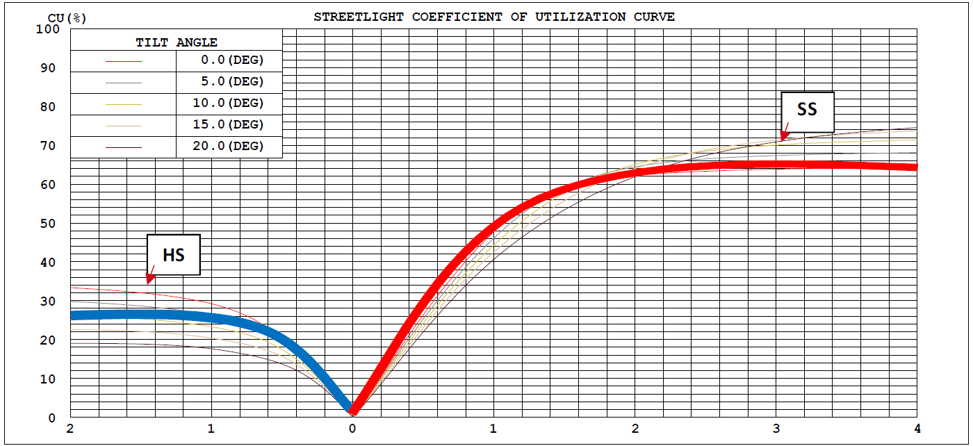
After the light comes out of the lamp, how much of it can fall on the “work surface” we need? Taking indoor luminaires as an example, part of the light emitted by the industrial lamp reaches the work surface directly, and part of the light hits the wall and ceiling and then reflects to the work surface, while the rest cannot reach the work surface (such as shining on the shelf). The utilization coefficient is the luminous flux (What’s luminous flux?) reaching the work surface divided by the luminous flux of the light source. In road lighting, it also has the concept of utilization coefficient, but it mostly appears in the form of coefficient of utilization curve. Because in road lighting, it is necessary to consider the distribution of light emitted by the lamp in the two directions of street side and house side. This article mainly discusses what is utilization coefficient, coefficient of utilization curve, what are the parameters that affect coefficient of utilization, the guiding significance of utilization coefficient, and how we can use coefficient of utilization curve to better select light distribution and arrange lamps in practical applications to obtain better lighting results. Let’s go into the text to get more information.
What’s coefficient of utilization?
Coefficient of utilization is also called utilization factor. It is a factor used to determine the lighting efficiency of a lighting fixture in a specific application. The calculation formula of the utilization factor is as follows: Coefficient of utilization = luminous flux projected onto the work surface / total luminous flux of the lamp. It is a measure of the efficiency of the lamp in transferring light energy to the work surface in a specific area. In indoor lighting, the utilization factor is affected by factors such as spectral distribution, space size (room index) and reflectivity of various indoor surfaces (walls, ceilings and floors). Ideally, the utilization factor of industrial and mining lamps used for indoor lighting can reach 1 or even slightly exceed 1; in road lighting, the utilization factor is related to factors such as spectral characteristics, lamp tilt angle, and boom length, and it often appears in the form of a coefficient of utilization curve. In indoor lighting, the lumen method is used to roughly estimate the lighting effect (illuminance) after the lamp is installed. This method is also called the utilization factor method because it uses the parameter of the utilization factor. Its calculation formula is: Eav (average illuminance) = Φ (luminous flux of a single lamp) x N (number of lamps) x CU (utilization factor) x K (maintenance factor) ÷ A (area). If you want to know more, you can refer to ZGSM’s corresponding blog – Lumen calculation method and its benefits.
Which affect the coefficient of utilization?
As for the coefficient of utilization value, we can get some general information from the text mentioned in the previous section. Taking indoor industrial lights as an example, when the light distribution is different, the space size is different, and the room surface reflectivity is different, the CU value will also change. The following is the utilization factor (which is also called coefficient of utilization) table of ZGSM Helios high bay lights (More about ZGSM Helios highbay lights). When the lens is different, the UF of the 60 degree beam angle is 0.82 at k (room index) = 0.6 and ρc = 0.8, ρw = 0.8 and ρf = 0.2, while the UF of the 120 degree beam angle is only 0.54. Because the larger the beam angle, the more light needs to pass through the wall and ceiling to the ground (target area). When the lens is the same (120 degrees), the different reflectivity of the wall, ceiling and floor will also affect the value of the UF value. And the differences are shown in the table. When the reflectivity and the room are the same, the smaller the room index (What’s room index?), the smaller the UF value. This is because the smaller the room index is, the smaller the room is (or the room is long and narrow). At this time, you can imagine that a large part of the light emitted by the lamp will shine on the surrounding walls, which will lead to a smaller UF value. So in street lamps, what factors are related to UF (coefficient of utilization)? ZGSM believes that it is mainly related to light distribution, lamp tilt angle and arm length. Let’s explain them one by one below.
| Beam angle 60 degree | ||||||||||
| REFLECTANCE | ||||||||||
| Ceiling | 0.8 | 0.8 | 0.8 | 0.7 | 0.7 | 0.7 | 0.5 | 0.5 | 0.5 | 0 |
| Walls | 0.7 | 0.5 | 0.3 | 0.7 | 0.5 | 0.3 | 0.7 | 0.5 | 0.3 | 0 |
| Working plane | 0.2 | 0.2 | 0.2 | 0.2 | 0.2 | 0.2 | 0.2 | 0.2 | 0.2 | 0 |
| ROOM INDEX | UTILIZATION FACTORS(PERCENT) k(RI) x RCR = 5 | |||||||||
| k = 0.60 | 82 | 75 | 70 | 81 | 74 | 70 | 80 | 74 | 70 | 66 |
| 0.8 | 90 | 83 | 79 | 89 | 83 | 79 | 88 | 82 | 78 | 74 |
| 1 | 95 | 89 | 85 | 95 | 89 | 85 | 93 | 89 | 84 | 80 |
| 1.25 | 100 | 94 | 90 | 99 | 94 | 90 | 97 | 92 | 89 | 84 |
| 1.5 | 103 | 98 | 94 | 102 | 97 | 93 | 100 | 95 | 92 | 87 |
| 2 | 107 | 102 | 98 | 105 | 101 | 97 | 102 | 99 | 96 | 90 |
| 2.5 | 109 | 104 | 101 | 107 | 103 | 100 | 104 | 101 | 98 | 92 |
| 3 | 110 | 107 | 103 | 109 | 105 | 102 | 105 | 102 | 100 | 94 |
| 4 | 113 | 110 | 107 | 111 | 108 | 106 | 107 | 105 | 103 | 96 |
| 5 | 114 | 111 | 109 | 112 | 110 | 108 | 108 | 106 | 105 | 97 |
| ROOM INDEX | UF(total) | Direct | ||||||||
| According to DIN EN 13032-2 2004 Suspended SHRNOM = 1.25 | ||||||||||
| Beam angle 120 degree | ||||||||||
| REFLECTANCE | ||||||||||
| Ceiling | 0.8 | 0.8 | 0.8 | 0.7 | 0.7 | 0.7 | 0.5 | 0.5 | 0.5 | 0 |
| Walls | 0.7 | 0.5 | 0.3 | 0.7 | 0.5 | 0.3 | 0.7 | 0.5 | 0.3 | 0 |
| Working plane | 0.2 | 0.2 | 0.2 | 0.2 | 0.2 | 0.2 | 0.2 | 0.2 | 0.2 | 0 |
| ROOM INDEX | Beam angle 120 degree – UTILIZATION FACTORS(PERCENT) k(RI) x RCR = 5 | |||||||||
| k = 0.60 | 54 | 42 | 35 | 53 | 42 | 35 | 52 | 41 | 34 | 28 |
| 0.8 | 67 | 55 | 47 | 66 | 54 | 47 | 64 | 54 | 47 | 40 |
| 1 | 78 | 67 | 60 | 76 | 66 | 59 | 74 | 67 | 59 | 52 |
| 1.25 | 86 | 76 | 69 | 84 | 75 | 69 | 82 | 74 | 68 | 61 |
| 1.5 | 91 | 82 | 75 | 89 | 81 | 75 | 86 | 79 | 74 | 67 |
| 2 | 98 | 91 | 85 | 96 | 89 | 84 | 93 | 87 | 83 | 75 |
| 2.5 | 101 | 95 | 89 | 100 | 93 | 88 | 96 | 91 | 86 | 79 |
| 3 | 105 | 99 | 94 | 102 | 97 | 93 | 99 | 94 | 90 | 82 |
| 4 | 108 | 103 | 99 | 106 | 101 | 97 | 101 | 98 | 95 | 86 |
| 5 | 110 | 105 | 102 | 107 | 103 | 100 | 103 | 100 | 97 | 88 |
| ROOM INDEX | UF(total) | Direct | ||||||||
| According to DIN EN 13032-2 2004 Suspended SHRNOM = 1.25 | ||||||||||
Light distribution of lamps
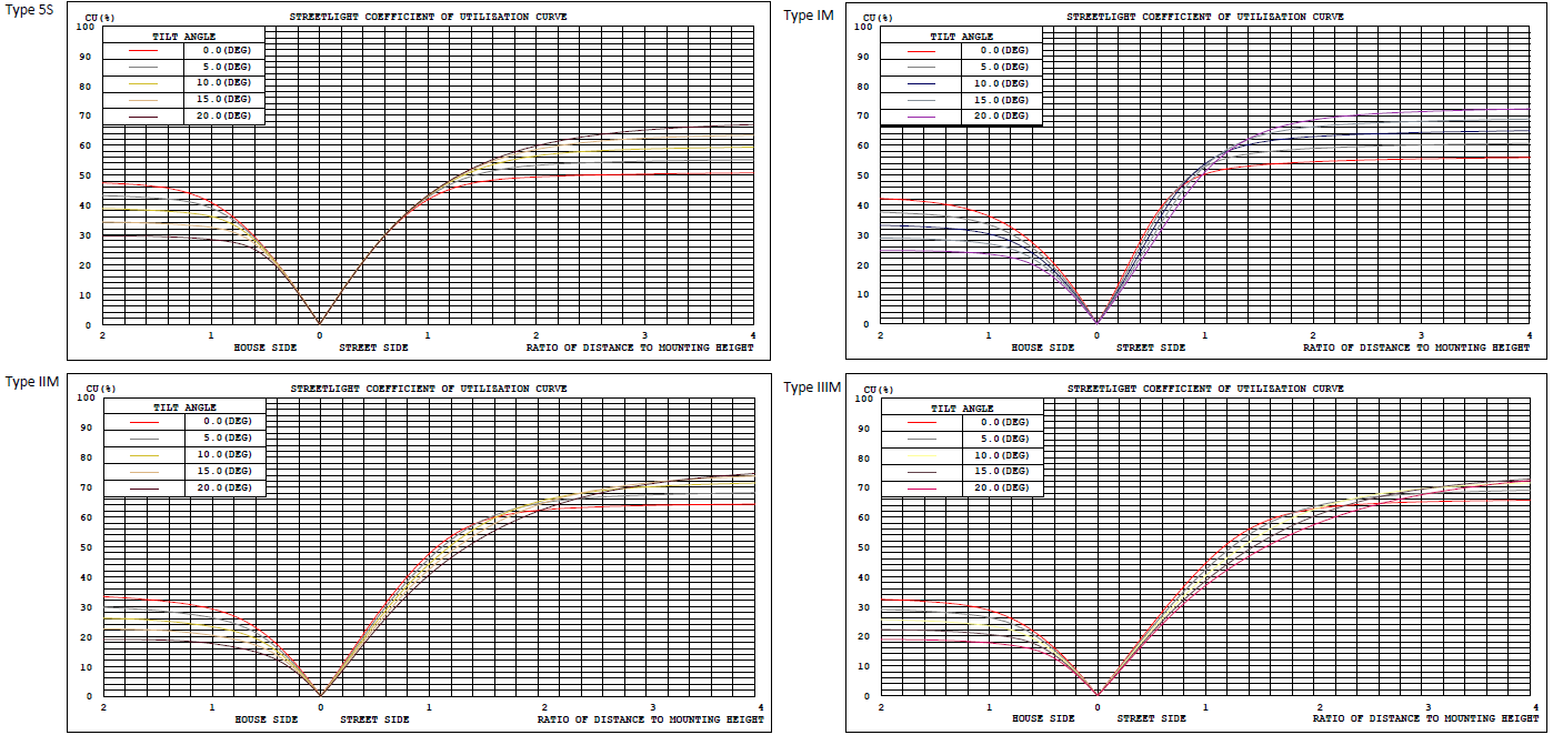
The light distribution curve of a lamp describes the light distribution characteristics of the luminous flux in space, which directly affects the coefficient of utilization (CU) of street lamps. By checking the light distribution, we can roughly know the distribution of the light emitted by the lamp on the road after actual installation. The CU value is a quantitative indicator, which measures the luminous flux emitted by the lamp to effectively reach the street side, house side and sky (LED lamps usually do not have this part of light). For example, in the spectrum of type VS, the proportion of light on the street side and house side is basically the same; while in the spectrum of type IIM (More about IESNA lighting distribution classification), the street side light accounts for about 65%, while the house side light accounts for only 30%. Please check details in below photo.
Tilt angle and installation height
The tilt angle of the lamp refers to the angle between the luminous surface of the lamp and the horizontal line (the ground), which directly affects the projection direction of the light and thus affects the coefficient of utilization curve. When the tilt angle is large, more light will be directed to the street side and the sky (Sky glow, a type of light pollution), while the proportion of the house side will decrease, as shown in the figure below. When the installation height changes, the distribution of light on the ground will change, showing that the corners farther away from the lamp are illuminated. It has no effect on the coefficient of utilization curve, but in actual applications, we need to pay attention to its impact when the ratio of installation height and road width changes. For example, for the same 7-meter road, when the height is 6 meters or 5 meters, the choice of light distribution needs to be changed according to the situation. The former often requires wider lateral light distribution than later, which we will explain in detail in the practical application section.
Boom length and setback of pole
The arm length and setback of the light pole will affect the illumination effect of the lamp after actual installation. The reason is that the light distribution of the street lamp in and around the road changes. We can imagine that when using a long arm, the lamp is often closer to the center of the road. Similarly, the smaller the setback, the closer the center point of the luminous surface of the lamp is to the center of the road. For more about the luminaire arrangement, please check ZGSM blog – Luminaire arrangement of street light LED. By observing the coefficient of utilization curve of the street lamp, when setback = 2 meters, without arm vs setback = 0 and arm = 2 meters, we can preliminarily estimate that 10% of the light originally directed to the rear of the lamp (house side) will be directed to the road surface (street side). Of course, we also need to pay attention to the problem that the light emitted by the road lamp with a long arm exceeds the boundary on the other side of the road.
Why coefficient of utilization matters?
In road lighting, the coefficient of utilization plays a significant role in guiding lighting design, energy conservation, and controlling the cost of street lighting solutions. The following elaborates on these aspects one by one.
Energy saving
In the coefficient of utilization curve of street lamps, we can divide the light emitted by street lamps into two parts, one part is directed to the house side, and the other part is directed to the street side. Generally, we believe that the part directed to the street side is useful light, and its proportion is usually between 0.5-1.0. Ideally, the higher the CU value, the better, but due to technical and cost considerations, it is often around 0.6-0.8. In order to achieve the same illuminance, the higher the CU, the lower the power of the lamp required, thereby achieving the purpose of energy saving.
Guide lighting design
The coefficient of utilization (CU) of a street is calculated by dividing the street width by the installation height of the lamp. In addition, when the tilt angle is different, the coefficient of utilization in house side and street side will also change. If the impact of vertical light distribution on the lighting simulation results is not considered, we can optimize the lighting design through the coefficient of utilization curve. For example, for wider roads, we can choose street lamps with larger light distribution in the coefficient of utilization in street side; for example, when the coefficient of utilization and road width are constant, we can optimize the lighting design (ZGSM lighting design service) by appropriately adjusting the boom length (if allowed), the height of the lamp pole (if allowed) and the elevation angle.
Cost control
Knowing the relevant information about CU, we can optimize the lighting design to achieve the desired lighting effect with lower wattage or fewer street lamps. This is very helpful for saving initial investment and reducing operation and maintenance costs. For example, using low-power street lamps can save electricity bills in the long term and meet the needs of sustainable development. In addition, low-power street lamps usually generate less heat, which helps to extend the life (More about lifetime of LED lights) of LED power supplies and LEDs, and is also very beneficial for reducing later maintenance. If it is a new project, you can analyze the CU curve to flexibly adjust the height of the lamp pole, the length of arm or the tilt angle to optimize the lighting design and avoid unreasonable lighting design to save cost.
Example to use coefficient of utilization to choose the lens for your project?
In the previous section, we know that coefficient of utilization can be used to guide lighting design. So what examples can be used to specifically illustrate this process? ZGSM will explain this through a project we encountered. The customer has specified the road parameters, and the following are two typical road layouts. One is 10.5 meters, with a boom length of 1.5 meters, a lamp pole 0.5 meters from the shoulder, no sidewalk, a lamp pole height of 8 meters, a one-side arrangement of lamps with M4 lighting class. Since the luminaire arrangement and road condition have been confirmed, the remaining variants are the light distribution and tilt angle of the lamps. ZGSM’s technical team analyzed three types of light distribution, type I, II and III, and the coefficient of utilization is as above. Through observation, we found that when the road width is 1.5 times the installation height (the value required is a bit bigger than width/height), the street side light accounts for 53%, 59%, and 58%, while the total street side light accounts for 57%, 63%, and 66%, respectively. Therefore, type II should be the most ideal choice, and it can also avoid too much light shining on the opposite side of the road. We verified the above analysis in the Dialux simulation, and the results are as follows: We can see that type I cannot illuminate the third lane (it mainly illuminates lanes 1 and 2 which caused lower light uniformity), type III can illuminate three lanes, but the luminance will drop a little (not listed), and type II has met the M4 lighting class (More about lighting class selection).

Layout of road 2 is almost the same as road 1, except that there is a 1-meter sidewalk on one side. The required lighting class is P3, and the arrangement of lamps is also one side arrangement. We use type III light distribution, and the results show that it can meet the P3 lighting class, but its glare value is too high. So what other methods are there? From the previous article, we know that when the tilt angle changes, the coefficient of utilization curve will change accordingly. By observing the curve, when the tilt angle is 5 degrees, the proportion of the lumen in 1.5 times of height in street side becomes lower, and the proportion of the lumen in between 1.5 and 2 times of height in street side increases. We can understand that the light on the motorway becomes less, while the light on the sidewalk becomes more. In Dialux, we use type II light distribution to verify whether this analysis is correct. The results show that the illumination of the sidewalk increases from 7.06 to 8.32 lux, that is, it meets the requirements of P3 lighting class. At the same time, the brightness of the motorway is reduced, but it can also meet the requirements. What’s more important is that the Ti value also meets the requirements of M4 lighting class, which further verifies the role of CU curve. In Dialux EVO, we can also use software to confirm the appropriate tilt angle and boom length. For more information, please refer to the corresponding blog – Dialux EVO for street lighting design.

Summary
The coefficient of utilization(CU) is a core indicator to measure the efficiency of a lamp (which is differs from luminous efficacy) in effectively projecting light to the target area. It is calculated as the ratio of the luminous flux of the effective working surface to the total luminous flux of the lamp. In road lighting, CU is presented in the form of a curve, and the light distribution on the street side and the building side must be considered at the same time. The key factors affecting CU include: the light distribution curve of the lamp, the tilt angle and the installation height (the tilt angle adjustment changes the light projection direction, and the height affects the coverage range), the length of the arm and the position of the lamp pole. Paying attention to the CU value can help you design your lighting and find energy-saving and optimized lighting solutions. In practical applications, we can select the appropriate light distribution for the current project by analyzing the coefficient of utilization. When the light distribution, road layout and luminaire arrangement are all certain, we can also adjust the tilt angle and the length of the cantilever arm (if possible) to affect the light distribution on the street side and the house side of the road to meet the project requirements. In short, understanding and flexibly applying CU can significantly improve the efficiency and economy of road lighting. For more information, please contact ZGSM.
Related Products
Related Blogs
Related Cases
People also ask
Author introduction
Hello Customers,
My name is Taylor Gong, I’m the product manager of ZGSM Tech. I have been in the LED lights industry for more than 13 years. Good at lighting design, street light system configuration, and bidding technology support. Feel free to contact us. I’m happy to provide you with the best service and products.
Email: [email protected] | WhatsApp: +8615068758483

