Mean time between failure of LED driver and the importance of MTBF
Mean time between failure of LED driver and the importance of MTBF
Introduction
In recent years, LED lighting technology and the number of applications employing it have rapidly developed, with its penetration increasing in public, residential, and commercial lighting. This is due to the numerous advantages LEDs offer the lighting industry, including high efficiency, durability, environmental friendliness, and reduced maintenance due to their long lifespan. All of these factors translate into energy and maintenance cost savings, but they all rely on the long lifespan of LED products. LED lifespan is typically expressed in terms like L70, L90, and LxxByy (What’s LxxByy?). For example, L70 > 100,000 hrs means the LED can maintain at least 70% of its initial luminous flux after 100,000 hrs of operation. 100,000 hrs is equivalent to an LED streetlight operating for 12 hours per night, maintaining this high efficiency(70%) after 22 years of operation. Furthermore, the LED driver lifespan is also of concern. Only if the LED driver remains stable over this time span can it provide a stable and continuous current/voltage input to the LED. So, what parameters can be used to indicate LED driver lifespan? The answer is MTBF, or Mean Time Between Failure. This article will explain its calculation criteria, influencing factors, and why we care about this parameter. Let’s get into the details and learn about the MBTF values of different LED drivers.
What’s mean time between failure (MTBF)?
The lifespan of an LED driver (How to choose LED driver?) can be expressed using MTBF. MTBF stands for Mean Time Between Failures and is a metric used to measure the reliability of a product, particularly an electrical appliance. And it’s measured in hours. It reflects the product’s time quality and its ability to maintain functionality within a specified timeframe. It can refer to the average operating time between two consecutive failures, also known as the Mean Time To Failures. It can also be the average time between the start of operation and the first failure of a new product under specified operating conditions. Generally speaking, a product with fewer failures is more reliable. For the same number of products over their lifecycle, a product with a higher MTBF value will experience fewer failures than one with a lower MTBF value. For repairable products, a higher MTBF value indicates a longer mean time between failures and better reliability. For non-repairable products, although repair is not possible after a failure, it can be used to describe the product’s average lifespan or mean time between failures. The mean time between failures (MTBF) applies only to periods of normal product operation and a constant failure rate, as shown in the figure below. We can see that the failure rate curve involves the Weibull parameter (β). When β < 1, the Weibull distribution describes premature failure of components. When β = 10, rapid wear and tear occurs. In theory, the failure rate curve for electronic equipment is a mixture of failure rate curves with different Weibull parameters, known as the bath cub curve.

How is mean time between failure (MTBF) calculated?
Research on the reliability and service life of LED drivers holds significant practical value. There are two methods for predicting the reliability and service life of LED drivers: one is the electronic equipment reliability estimation method based on MIL-HDBK-217F, a handbook published by the U.S. military, hence the standard prefix MIL-HDBK; the other is an experimental accelerated life testing method. The former was initially used for reliability testing of military equipment but is now also employed by many LED driver suppliers (such as Osram, Philips, and Inventronics) to test the reliability of their products. The latter simulates the stability and reliability of LED driver components under different temperature (Working temperature of LED driver), humidity, voltage, and continuous switching cycle conditions. By applying high stress (such as high temperature, high humidity, high voltage, etc.) to accelerate product aging, reliability can be predicted in a shorter timeframe, and MTBF (Mean Time Between Failure) can be obtained through Weibull analysis. This article focuses on the former method, as the author has observed that most prominent LED driver manufacturers adopt this approach, while the latter is rarely mentioned.
Philips conducted MTBF testing on its Xitanium series LED drivers, referencing the standard MIL-HDBK-217F. As stated, for a typical 150W Xitanium LED driver operating at a case temperature of approximately 50°C, the theoretical failure rate is 500 PPM/1000 hours, meaning that the Xitanium series LED driver has a failure rate of 500 PPM over 1000 hours of use. This translates to 500 failures per million units within 1000 hours. From this, we calculate MTBF = Total operating time / Number of failures = 1000 × 1,000,000 / 500, which is approximately 2 million hours. It is important to note that this parameter does not indicate that a single LED driver will fail after 2,000,000 hours of use, but rather represents the probability of failure for a specific number of LED drivers over a certain period of time. For example, if our project plans to use 2,000 pieces Xitanium series LED drivers, with a project lifespan of 10 years and daily operation for 12 hours, we can estimate the number of faulty units after 10 years, which is 10 × 365 × 12 × 2,000 / 2,000,000 = 43.8.
Why we cares about MTBF of LED driver?
Improve safety
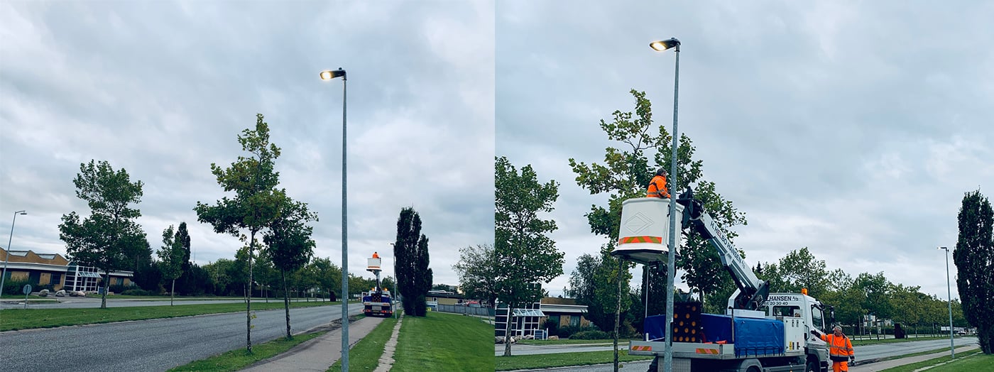
A high MTBF for an LED driver means that the LED driver experiences fewer failures over its entire lifespan while providing the required current/voltage input to the LED. Unlike LED lumen depreciation (What’s Light decay and constant lumen output?), which occurs gradually, LED driver failures are often catastrophic. The luminaire may flicker or completely shut down, resulting in the inability to provide proper public lighting. Take Inventronics EUM DG and EBS BT2 power supplies as examples. The former has an MTBF of 473,000 hours, while the latter has an MTBF of 203,000 hours. Based on the results provided, the former clearly has a significant advantage. For a project involving 1,000 pieces streetlights, after five years of use, the estimated failure rate for the former is 4.6%, while the latter reaches as high as 10.8%. If additional factors such as surges are considered, the latter would require extensive repairs after five years. If maintenance is not performed promptly, the reliability of the lighting system will decline, making it unable to provide continuous and stable illumination. This would inevitably increase road safety hazards and even raise the probability of traffic accidents.
Higher MF with higher MTBF
When calculating the maintenance factor, we need to apply the lamp survival factor parameter, abbreviated as LSF. It represents the probability that the light source and/or luminaire will continue to operate at a given time. LED light sources typically have a low failure rate and are generally not considered. The primary probability of luminaire failure stems from the LED driver. For details, please refer to Maintenance factor in illumination/lighting. It is straightforward to understand that LSF = 1 – failure rate (over the project duration). For example, in a project with a 5-year lifespan using Inventronics EUM series power supply, which has an MTBF of 750,000 hours, the failure rate can be understood as 0.667% per 5,000 hours. Taking an example where the lighting system is operated for 12 hours daily, the probability of failure over the entire project cycle is calculated as 0.667% × 12 × 365 × 5 / 5,000 = 2.92%, resulting in LSF = 100% – 2.92% = 97.08%. Conversely, the smaller the MTBF value, the smaller the LSF value. In the article on the maintenance factor, we know that the higher the LSF value, the higher the MF value. Therefore, during the project cycle, the impact of insufficient lighting caused by LED driver failures is minimized, and we can often achieve the required lighting effect with fewer fixtures. This is very helpful for reducing initial lighting fixture investment. Similarly, if spot replacement is used for lighting fixture maintenance, although the LSF value is 1, we still need to replace more fixtures with low MTBF values, which will also increase future maintenance costs.
Enhance user experience and brand influence
As we have mentioned, a high MTBF value indicates a low failure rate for LED drivers. Users naturally place greater trust in such products and expect them to remain reliable for years without frequent failures. With fewer failures, customers typically do not need to replace or maintain the LED drivers. Imagine the difference in user experience between having to replace light bulbs multiple times a year and only needing to replace lighting fixtures every few years. Similarly, LED driver and LED fixture manufacturers (ZGSM and its products) also aim to improve product quality to ensure a high MTBF. This is highly beneficial for enhancing product reputation, thereby attracting an increasing number of customers to choose such products. Conversely, if your LED driver experiences a failure rate of nearly 20% or higher after several years of use, we(consumer) believe users will lose confidence in your product.
Which effect the MTBF of LED driver?
Quality of components
One of the major challenges in LED driver manufacturing is component selection. For LED driver manufacturers, each component must be carefully selected and undergo extensive design certification, testing, and internal long-term reliability checks. A rigorous supplier selection process and long-term partnerships with suppliers ensure that only the highest quality components are used in LED drivers. For example, electrolytic capacitors are a weak link in LED driver lifespan, as their lifespan is directly related to temperature. At high temperatures, different materials expand at varying rates, leading to internal tensile or compressive stresses. Therefore, selecting capacitors with good temperature characteristics is highly beneficial for improving the MTBF (Mean Time Between Failure) of LED drivers. Additionally, from a design perspective, conducting a thorough analysis of component stress and implementing adequate derating measures ensures that the LED driver achieves extremely high reliability. For instance, for an LED driver with a maximum output power of 100W, we can reserve 10% (actual output of 90W) in practical use to achieve industry-leading service life.
Ambient temperature
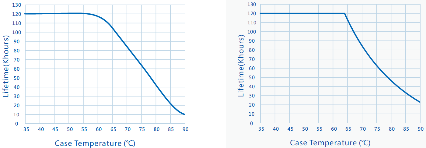
LED lamps are clearly marked with their operating temperature. This is because temperatures that are too low can prevent them from starting, while temperatures that are too high can cause LED failure and malfunction. The main cause of this failure is high temperatures that can cause problems in inductors, optocouplers, and printed circuit boards. These failures include accelerated degradation of insulation materials at high temperatures, increasing the risk of short circuits; optocoupler failure at high temperatures, leading to feedback circuit failure; and stress changes on PCB solder joints caused by high temperatures, resulting in poor solder joints. Therefore, for LED lamps designed to operate in high-temperature environments, choosing a high-temperature-resistant LED driver is equally important. For example, Sosen’s constant-current LED drivers SS-100VB and SS-100VP are advertised as being more suitable for high-temperature operation. The following lifespan curves show that the former’s lifespan is significantly reduced when its Tc reaches around 60°C. The latter, on the other hand, is suitable for higher-temperature environments, with a maximum operating temperature of 90°C. ZGSM’s HB13 high-bay lamp (More about ZGSM HB13 series highbay) uses this series of LED drivers, suitable for high-temperature forging plants, glass factories, smelters, and other applications.
Product design and protection mechanisms
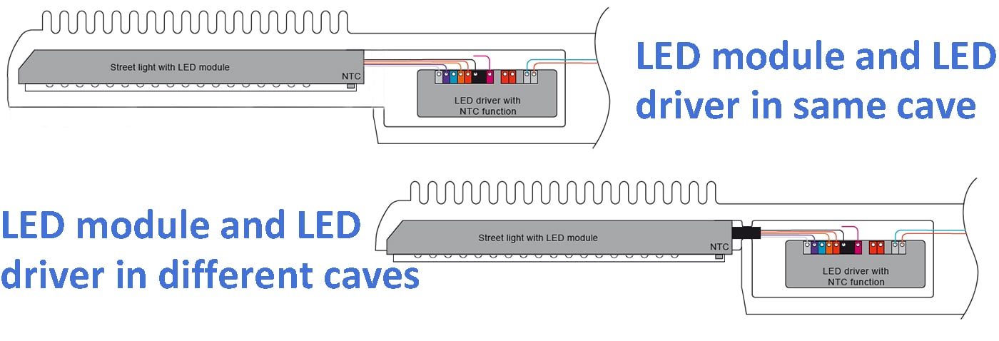
LED luminaire design is equally important for extending the life of the LED driver. The LED driver and LED module are often integrated into a single housing, with the former continuously providing voltage and current to the latter throughout its lifecycle. However, both generate heat, and heat buildup can inevitably lead to malfunction in the luminaire. Ideally, the two components should be placed independently, minimizing interference (see the figure below). Furthermore, after the luminaire is designed, it needs to be tested to simulate actual operating conditions. For example, the ISTMT test requires the luminaire to be tested at either 25°C or 50°C for both the LED driver’s Tc point temperature and the LEDs’ Ts point temperature. The Tc point determines the mean time between failure (MTBF) and the LEDs’ lumen degradation. ZGSM typically requires a Tc value 5-10°C below the specified maximum Tc. For example, the EUM DG series has a Tc warranty temperature of 80°C, while ZGSM requires a measured Tc value of less than 70°C at 25°C. Furthermore, if the LED driver has a high-temperature derating function, this can be used to cut output when necessary, thereby extending its life. If the driver has more advanced features (such as an NTC), these features can be enabled. For example, when a lamp is operating abnormally, the NTC function (NTC and its application in street lights) can detect the temperature of the casing or LEDs. When it exceeds the limit, the output current of the LED driver will be reduced to reduce power loss, and ultimately ensure that the temperature of the internal components of the driver does not exceed the threshold, thereby improving the reliability and service life of the driver.
ZGSM LED lights with long MTBF value
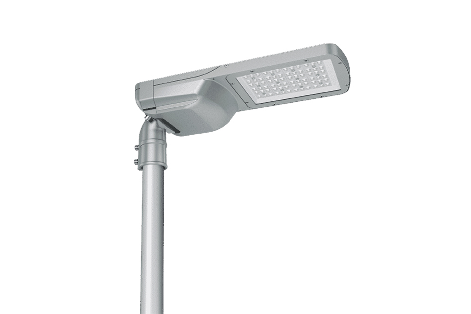
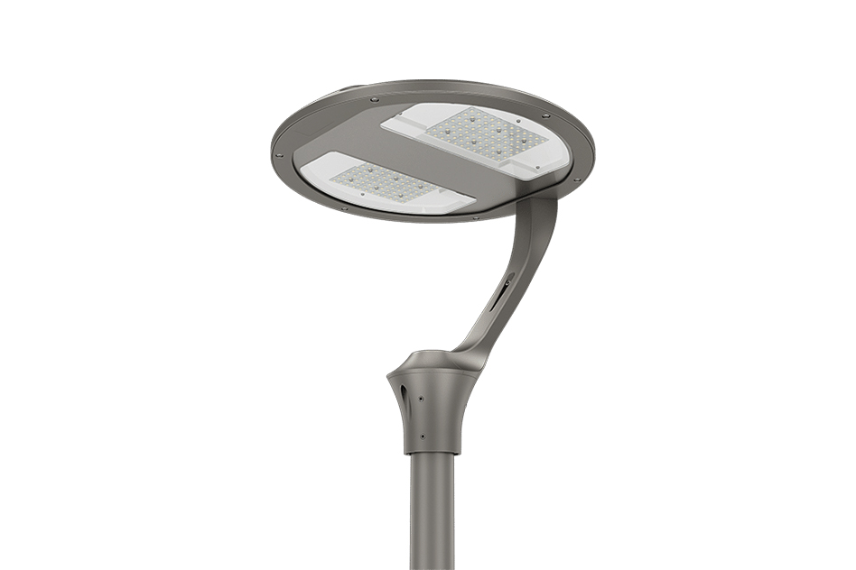
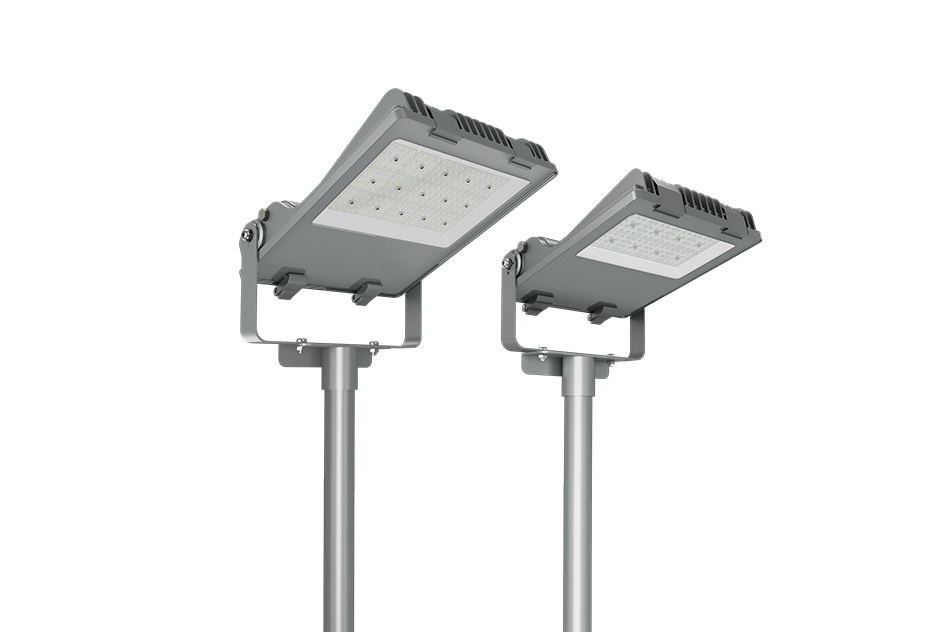
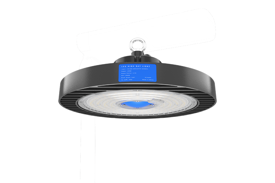
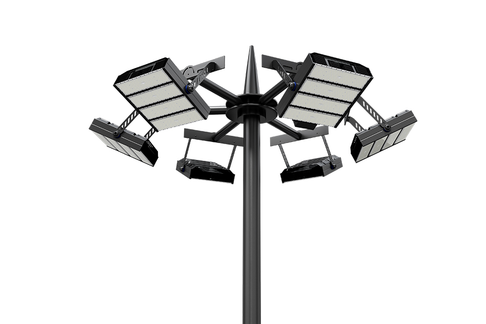
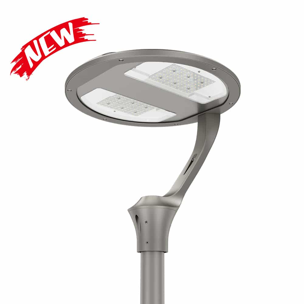
Different LED drivers have different mean time between failure values. ZGSM‘s LED products can be with LED drivers from different brands and series, such as Inventronics, Philips, Osram, Meanwell, Done, and others. The MTBF of different series of Inventronics LED drivers varies greatly. For example, the EUM DG series has an MTBF of approximately 300,000-600,000 hrs, while the EUM MG series (suit for street lights with motion sensor) has an even higher MTBF of up to 1,500,000 hrs. Philips’ high-end series can reach 2,000,000 hrs, while Meanwell’s XLG only has a 1,000,000 hrs (based on the Telcordia SR-332 standard, and even lower if it tests with the MIL-HDBK standard). If your project has specific MTBF requirements, consult ZGSM for more information. Below are ZGSM’s different series of LED products; click on the image for more details.
Summary
LED drivers are key components in LED lighting devices, powering and controlling LEDs to achieve the desired lighting effect. They are also the weakest link in LED lighting systems, and their service life significantly impacts the lifespan of the entire lighting system. This article systematically explores the Mean Time Between Failures (MTBF) of LED drivers and how to calculate it. If you want your luminaire to operate without failure for a long time, choosing a luminaire with a high MTBF is a good choice. Using LED drivers with high MTBF in the road lighting industry offers many practical benefits, including improving public safety, reducing maintenance costs ( Learn more about LED street light maintenance and how it helps reduce operating costs. ), and enhancing brand competitiveness. For LED driver manufacturers, selecting high-quality components is crucial for improving MTBF. It is equally important for LED manufacturers to optimize luminaire design to ensure stable operation of the LED driver within the specified ambient temperature. MTBF is not just a technical parameter; it reflects the manufacturer’s overall strength and is crucial for cost control (street light cost) and safety management throughout the project lifecycle. Contact ZGSM for more information.
Related Products
Related Blogs
Related Cases
People also ask
Author introduction

Hello Customers,
My name is Taylor Gong, I’m the product manager of ZGSM Tech. I have been in the LED lights industry for more than 13 years. Good at lighting design, street light system configuration, and bidding technology support. Feel free to contact us. I’m happy to provide you with the best service and products.
Email: [email protected] | WhatsApp: +8615068758483

